A fiber optic channel can contain components that individually meet their specifications and still exceed its overall optical loss budget. As network architectures incorporate more patching stages, multi-fiber assemblies, and intermediate connections, maintaining end-to-end performance becomes more demanding.
This is particularly relevant in large data centers and AI computing clusters, where optical infrastructure may connect equipment across multiple network tiers. Each additional interface introduces another contribution to channel loss, while different cabling configurations create dependencies that must remain consistent throughout the system.
The challenge is no longer limited to selecting components with acceptable performance. Engineers must also understand how those components interact across the complete optical path.
A Connection Is Part of a Larger System
In a basic point-to-point optical channel, performance depends on the fiber, connector interfaces, and transmission equipment. Introducing intermediate patch panels changes the equation. Each additional mated connection contributes insertion loss and creates another location where fiber mapping must remain correct.
These effects accumulate as the channel becomes more complex. A connector may perform comfortably within its specified insertion-loss limit, yet the combined attenuation of several interfaces can consume a significant portion of the available optical power budget.
For network architects, this creates an important distinction between component compliance and channel performance. Individual connectors and adapters must meet their requirements, but the completed optical path must also operate within the limits established by the application.
Optical Loss Across the Channel
Insertion loss at a mated connector interface depends on factors such as fiber alignment, end-face geometry, cleanliness, and connection quality. In architectures with multiple patching stages, each interface contributes to the total channel loss.
Consider two hypothetical designs using an illustrative allocation of 0.3 dB per mated interface.
| Architecture | Mated interfaces | Allocated connector loss |
| Channel A | 2 | 0.6 dB |
| Channel B | 6 | 1.8 dB |
Channel B requires an additional 1.2 dB of connector-loss allowance before accounting for fiber attenuation, splices, or other losses.
These figures represent design allocations rather than measured product performance. Actual loss requirements depend on the optical application and the components selected.
The comparison demonstrates why connection count must be considered early in network planning. Adding patching flexibility may improve operational management, but it also increases the number of interfaces that must fit within the optical budget.
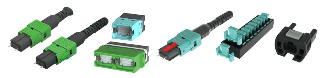
Low-loss connectivity becomes particularly useful when those budgets are constrained. Suncall’s MPO connector portfolio includes standard and low-loss configurations, giving engineers options when selecting components for channels with different performance requirements.
The objective is not necessarily to specify the lowest-loss component everywhere. It is to select appropriate performance characteristics based on the complete channel design.
Polarity and Configuration Control at Scale
Optical attenuation is only one concern. Correct fiber mapping becomes increasingly important as networks incorporate multi-fiber connectors, trunk assemblies, and breakout configurations.
In a duplex link, polarity ensures that the transmit fiber at one end reaches the corresponding receive path at the other. Parallel optical systems require correct mapping across multiple transmit and receive lanes, making configuration accuracy essential.
Consider a data center transitioning to higher-speed parallel optics. Existing patching infrastructure may be combined with new MPO trunk assemblies, breakout connections, or equipment using different lane configurations. The connectors may be physically compatible, but an incorrectly selected polarity arrangement can prevent the intended end-to-end connection.
The problem may not be visible through ordinary connector inspection. Correct housing geometry and acceptable insertion loss do not guarantee correct fiber mapping.
This places greater importance on selecting the appropriate cable assemblies, adapter keying arrangements, and polarity configurations before installation.
Field flexibility can also be valuable when requirements change. Suncall’s MPO Multifunction Connector and Exchanger Tool Set supports connector gender and polarity changes in the field, allowing compatible assemblies to be reconfigured without replacing the entire connector assembly.
Such capabilities do not eliminate the need for polarity planning. They provide additional options when an installation requires an approved configuration adjustment.
More Components Create More Configuration Dependencies
Modern fiber infrastructure rarely consists of a single connector type or cabling arrangement. A project may involve multiple fiber counts, cable lengths, connector genders, polish types, and adapter keying options.
As these variations increase, so does the importance of configuration management.
Two MPO trunk assemblies, for example, may appear similar while serving different polarity requirements. An incorrect assembly selection can introduce a mapping problem that only becomes apparent during commissioning.
The same principle applies to connector and adapter compatibility. Mechanical fit is necessary, but it does not establish that every configuration is appropriate for a particular system.
Accurate documentation, clear labeling, and defined component specifications help reduce these risks. They also become increasingly important when infrastructure is expanded or modified over time.
The engineering objective is to preserve design flexibility without allowing configuration uncertainty to increase alongside connection counts.
Channel-Level Verification Matters
Component specifications describe expected performance under defined conditions. Once connectors, cables, and adapters are assembled into an installed channel, the complete system requires verification.
Different tests address different requirements.
Insertion loss testing determines whether the completed channel satisfies its attenuation budget. Polarity verification confirms that fibers follow the intended end-to-end mapping. End-face inspection helps identify contamination or physical damage that may affect connection quality.
These checks complement one another. A channel can meet its insertion-loss requirement while containing an incorrect polarity arrangement. Conversely, correct fiber mapping does not guarantee acceptable optical attenuation.
For complex installations, acceptance procedures should define both the required measurements and the criteria used to evaluate results. This provides a clearer basis for commissioning and future troubleshooting.
Testing also establishes a useful reference point. When the network is modified, documented results can help distinguish existing channel characteristics from changes introduced during expansion or maintenance.
Engineering for the Complete Connection Path
As optical networks incorporate more patching stages, multi-fiber assemblies, and equipment configurations, engineers must consider how individual components affect the performance of the complete channel.
Connector specifications remain important, but they cannot replace careful loss budgeting, polarity planning, and configuration control. A component that performs well independently must still be selected and integrated correctly within the intended architecture.
These requirements also influence component development and selection. Suncall America’s approach combines precision manufacturing with engineering collaboration, helping customers evaluate connector and adapter solutions against the optical and mechanical demands of their applications.
As networks evolve, maintaining predictable performance requires attention to the relationships between components, not just their individual specifications. Understanding those relationships early helps preserve performance margins, reduce configuration uncertainty, and support future expansion.
Suncall America develops precision fiber optic connectors and adapters used in high-density network environments. This article is part of an ongoing effort to share practical insights on connectivity challenges in modern data center infrastructure.*